Transformer
A transformer is an electrical device that transfers energy from one circuit to another by magnetic coupling with no moving parts. A transformer comprises two or more coupled windings, or a single tapped winding and, in most cases, a magnetic core to concentrate magnetic flux. An alternating current in one winding creates a time-varying magnetic flux in the core, which induces a voltage in the other windings. Transformers are used to convert between high and low voltages, to change impedance, and to provide electrical isolation between circuits.
Overview
The transformer is one of the simplest of electrical devices. Its basic design, materials, and principles have changed little over the last one hundred years, yet transformer designs and materials continue to be improved. Transformers are essential for high voltage power transmission, providing an economical means of transmitting power over large distances. The simplicity, reliability, and economy of conversion of voltages by transformers was the principal factor in the selection of alternating current power transmission in the "War of Currents" in the late 1880s.
Audio-frequency transformers, then referred to as repeating coils, were used by the earliest experimenters in the development of the telephone. While some early electronics applications of the transformer have been replaced by alternative techniques, transformers are still found in many electronic devices.
Transformers come in a range of sizes from a thumbnail-sized coupling transformer hidden inside a stage microphone to huge gigawatt units used to interconnect large portions of national power grids. All operate with the same basic principles and with many similarities in their parts.
Transformers alone cannot do the following:
- Convert DC to AC or vice versa
- Change the voltage or current of DC
- Change the AC supply frequency.
However, transformers are components of the systems that perform all these functions.
An analogy
The transformer may be considered as a simple two-wheel 'gearbox' for electrical voltage and current. The primary winding is analogous to the input shaft and the secondary winding to the output shaft. In this analogy, current is equivalent to shaft speed, voltage to shaft torque. In a gearbox, mechanical power (speed multiplied by torque) is constant (neglecting losses) and is equivalent to electrical power (voltage multiplied by current) which is also constant.
The gear ratio is equivalent to the transformer step-up or step-down ratio. A step-up transformer acts analogously to a reduction gear (in which mechanical power is transferred from a small, rapidly rotating gear to a large, slowly rotating gear): it trades current (speed) for voltage (torque), by transferring power from a primary coil to a secondary coil having more turns. A step-down transformer acts analogously to a multiplier gear (in which mechanical power is transferred from a large gear to a small gear): it trades voltage (torque) for current (speed), by transferring power from a primary coil to a secondary coil having fewer turns.Basic principles
Coupling by mutual induction
A simple transformer consists of two electrical conductors called the primary winding and the secondary winding. These two windings can be considered as a pair of mutually coupled coils. Energy is coupled between the windings by the time-varying magnetic flux that passes through (links) both primary and secondary windings.
Elementary analysis
A step-down transformer showing magnetising flux in the core
is applied to the primary winding of
turns, a current will flow in it producing a magnetomotive force (MMF). Just as an electromotive force (EMF) drives current around an electric circuit, so MMF tries to drive magnetic flux through a magnetic circuit. The primary MMF produces a varying magnetic flux
in the core, and, with an open circuit secondary winding, induces a back electromotive force (EMF) in opposition to
and
where
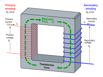
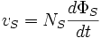
- vP and vS are the voltages across the primary winding and secondary winding,
- NP and NS are the numbers of turns in the primary winding and secondary winding,
- dΦP / dt and dΦS / dt are the derivatives of the flux with respect to time of the primary and secondary windings.
Saying that the primary and secondary windings are perfectly coupled is equivalent to saying that
. Substituting and solving for the voltages shows that:

where
- vp and vs are voltages across primary and secondary,
- Np and Ns are the numbers of turns in the primary and secondary , respectively.
Hence in an ideal transformer, the ratio of the primary and secondary voltages is equal to the ratio of the number of turns in their windings, or alternatively, the voltage per turn is the same for both windings. The ratio of the currents in the primary and secondary circuits is inversely proportional to the turns ratio. This leads to the most common use of the transformer: to convert electrical energy at one voltage to energy at a different voltage by means of windings with different numbers of turns. In a practical transformer, the higher-voltage winding will have more turns, of smaller conductor cross-section, than the lower-voltage windings.
The EMF in the secondary winding, if connected to an electrical circuit, will cause current to flow in the secondary circuit. The MMF produced by current in the secondary opposes the MMF of the primary and so tends to cancel the flux in the core. Since the reduced flux reduces the EMF induced in the primary winding, increased current flows in the primary circuit. The resulting increase in MMF due to the primary current offsets the effect of the opposing secondary MMF. In this way, the electrical energy fed into the primary winding is delivered to the secondary winding.
For example, suppose a power of 50 watts is supplied to a resistive load from a transformer with a turns ratio of 25:2.
- P = EI (power = electromotive force × current)
- 50 W = 2 V × 25 A in the primary circuit
- Now with transformer change:
- 50 W = 25 V × 2 A in the secondary circuit.
Alternative transformer analysis
This treats the windings as a pair of mutually coupled coils with both primary and secondary windings passing currents. In an ideal transformer the primary MMF must equal the secondary MMF, and since these are in opposite directions, they cancel so that there is no overall resultant flux in the core. That this is so can be seen by realising that any unopposed primary emf would create a large primary current and therefore a large flux in the core due to the primary winding. However, this large flux would necessarily cause a large current to flow in the secondary circuit and this current must create an opposing flux that effectively cancels the initiating primary flux. In a non-ideal transformer, the resultant flux in the core is that needed to magnetise the core. This is called the magnetising flux.
Direct current
Transformers should not be driven with DC nor, generally, have any DC component present at the input. Relatively small amounts of direct current can cause core saturation and thus prevent proper operation. Also, since a DC voltage source would not give a time-varying flux in the core, no induced counter-EMF would be generated and so current flow into the transformer would be limited only by the series resistance of the windings. In this situation, the transformer would heat until the transformer either reaches thermal equilibrium or is destroyed. This principle is actually exploited when large power transformers must be dried (have condensation and other water removed from their windings) -- they are simply heated using DC.
For the exact same reason, transformers should generally not have DC components present in their output windings. The one notable violation of this rule occurs with half-wave rectifiers, but these circuits are usually extremely limited in output power anyway. Full-wave rectifiers, by comparison, impose no DC component on the transformer and so are capable of much higher power levels.
The Universal emf equation
If the flux in the core is sinusoidal, the relationship for either winding between its number of turns, voltage, magnetic flux density and core cross-sectional area is given by the universal emf equation (from Faraday's law):
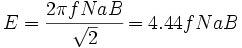
where
- E is the sinusoidal root mean square voltage of the winding,
- f is the frequency in hertz,
- N is the number of turns of wire,
- a is the cross-sectional area of the core in square meters and
- B is the peak magnetic flux density in teslas (and therefore
 is the root mean square flux density).
Invention
Those credited with the invention of the transformer include:
- Michael Faraday, who invented an 'induction ring' on August 29, 1831. This was the first transformer, although Faraday used it only to demonstrate the principle of electromagnetic induction and did not foresee the use to which it would eventually be put.
- Lucien Gaulard and John Dixon Gibbs, who first exhibited a device called a 'secondary generator' in London in 1881 and then sold the idea to American company Westinghouse. This may have been the first practical power transformer, but was not the first transformer of any kind. They also exhibited the invention in Turin in 1884, where it was adopted for an electric lighting system. Their early devices used an open iron core, which was later abandoned in favour of a more efficient circular core with a closed magnetic path.
- William Stanley, an engineer for Westinghouse, who built the first practical device in 1885 after George Westinghouse bought Gaulard and Gibbs' patents. The core was made from interlocking E-shaped iron plates. This design was first used commercially in 1886.
- Hungarian engineers Károly Zipernowsky, Ottó Bláthy and Miksa Déri at the Ganz company in Budapest in 1885, who created the efficient "ZBD" model based on the design by Gaulard and Gibbs.
- Nikola Tesla in 1891 invented the Tesla coil, which is a high-voltage, air-core, dual-tuned resonant transformer for generating very high voltages at high frequency.
Many others have patents on transformers.
Practical considerations
Classifications
Transformers are adapted to numerous engineering applications and may be classified in many ways:
- By power level (from fraction of a volt-ampere(VA) to over a thousand MVA),
- By application (power supply, impedance matching, circuit isolation),
- By frequency range (power, audio, radio frequency(RF))
- By voltage class (a few volts to about 750 kilovolts)
- By cooling type (air cooled, oil filled, fan cooled, water cooled, etc.)
- By purpose (rectifier, arc furnace, amplifier output, etc.).
- By ratio of the number of turns in the coils
- Step-up
- The secondary has more turns than the primary.
- Step-down
- The secondary has fewer turns than the primary.
- Isolating
- Intended to transform from one voltage to the same voltage. The two coils have approximately equal numbers of turns, although often there is a slight difference in the number of turns, in order to compensate for losses (otherwise the output voltage would be a little less than, rather than the same as, the input voltage).
- Variable
- The primary and secondary have an adjustable number of turns which can be selected without reconnecting the transformer.
- Distribution transformers are generally used in power distribution and transmission systems.
Distribution transformers contain the highest voltage so as to minimize power loss during transmission. The high voltage is later lowered using home supply transformers so as minimize danger associated with high voltage power transmission lines.
Circuit symbols
Standard symbols
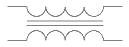 |
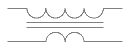
Transformer with two windings and iron core. |
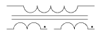 |
Transformer with three windings. The dots show the adjacent ends of the windings. |
 |
Step-down or step-up transformer. The symbol shows which winding has more turns, |
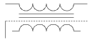 |
Transformer with electrostatic screen, which prevents capacitive coupling between the windings. |
Losses
An ideal transformer would have no losses, and would therefore be 100% efficient. In practice, energy is dissipated due both to the resistance of the windings (known as copper loss), and to magnetic effects primarily attributable to the core (known as iron loss). Transformers are, in general, highly efficient. Large power transformers (over 50 MVA) may attain an efficiency as high as 99.75%. Small transformers, such as a plug-in "power brick" used to power small consumer electronics, may be less than 85% efficient.
Transformer losses arise from:
- Winding resistance
Current flowing through the windings causes resistive heating of the conductors. At higher frequencies, skin effect and proximity effect create additional winding resistance and losses.
- Eddy currents
Induced eddy currents circulate within the core, causing resistive heating.
- Hysteresis losses
Each time the magnetic field is reversed, a small amount of energy is lost to hysteresis within the magnetic core. The amount of hysteresis is a function of the particular core material.
- Magnetostriction
Magnetic flux in the core causes it to physically expand and contract slightly with the alternating magnetic field, an effect known as magnetostriction. This in turn causes losses due to frictional heating in susceptible ferromagnetic cores.
- Mechanical losses
In addition to magnetostriction, the alternating magnetic field causes fluctuating electromagnetic forces between the primary and secondary windings. These incite vibrations within nearby metalwork, creating a familiar humming or buzzing noise, and consuming a small amount of power.
- Stray losses
Not all the magnetic field produced by the primary is intercepted by the secondary. A portion of the leakage flux may induce eddy currents within nearby conductive objects, such as the transformer's support structure, and be converted to heat.
- Cooling system
Large power transformers may be equipped with cooling fans, oil pumps or water-cooled heat exchangers designed to remove the heat caused by copper and iron losses. The power used to operate the cooling system is typically considered part of the losses of the transformer.
Operation at different frequencies
The universal transformer emf equation shows that, for a given voltage, core flux density is inversely proportional to frequency. Thus, by operating at higher frequencies, transformers can be physically more compact without reaching saturation, and a given core is able to transfer more power. Generally, operation of a transformer at a higher frequency than that for which it was designed will lead to reduced magnetising (no load primary) current and safe operation. At a frequency lower than the design value, the magnetising current may increase to an excessive level, and such operation is not recommended and may be dangerous.
- Traditional cores (silicon steel) develop more thermal losses as the operating frequency is increased.
- Ferrite cores are typically used for frequencies above 1kHz.
- Aircraft traditionally use 400 Hz power systems since the slight increase in thermal losses is more than offset by reduced weight.
- Military gear includes 400 Hz (and other frequencies) to supply power for radar or servomechanisms.
- Flyback transformers are built using ferrite cores. They supply high voltage to the CRTs at the frequency of the horizontal oscillator. In the case of television sets, this is about 15.7kHz. It may be as high as 75 - 120kHz for high-resolution computer monitors.
- Switching power supply transformers usually operate between 50-1000 kHz .
- The tiny cores found in wristwatch backlight power supplies produce audible sound (about 1 kHz).
Operation of a power transformer at other than its design frequency may require assessment of voltages, losses, and cooling to establish if safe operation is practical. For example, transformers at hydroelectric generating stations may be equipped with over-excitation protection, so-called "volts per hertz" protection relays, to protect the transformer from overvoltage at higher-than-rated frequency which may occur if a generator loses its connected load.
Construction
Cores
Steel cores
Laminated core transformer showing edge of laminations at top of unit.
Transformers for use at power or audio frequencies have cores made of many thin laminations of silicon steel. By concentrating the magnetic flux, more of it is usefully linked by both primary and secondary windings. Since the steel core is conductive, it, too, has currents induced in it by the changing magnetic flux. Each layer is insulated from the adjacent layer to reduce the energy lost to eddy current heating of the core. A typical laminated core is made from E-shaped and I-shaped pieces, leading to the name "EI transformer".
A steel core's magnetic hysteresis means that it retains a static magnetic field when power is removed. When power is then reapplied, the residual field will cause a high inrush current until the effect of the remanent magnetism is reduced, usually after a few cycles of the applied alternating current. Overcurrent protection devices such as fuses must be selected to allow this harmless inrush to pass. On transformers connected to long overhead power transmission lines, induced currents due to geomagnetic disturbances during solar storms can cause saturation of the core, and false operation of transformer protection devices.
Distribution transformers can achieve low off-load losses by using cores made with amorphous (non-crystalline) steel, so-called "metal glasses" — the high cost of the core material is offset by the lower losses incurred at light load, over the life of the transformer. In order to maintain good voltage regulation, distribution transformers are designed to have very low leakage inductance.
Certain special purpose transformers use long magnetic paths, insert air gaps, or add magnetic shunts (which bypass a portion of magnetic flux that would otherwise link the primary and secondary windings) in order to intentionally add leakage inductance. The additional leakage inductance limits the secondary winding's short circuit current to a safe, or a controlled, level. This technique is used to stabilize the output current for loads that exhibit negative resistance such as electric arcs, mercury vapor lamps, and neon signs, or safely handle loads that may become periodically short-circuited such as electric arc welders.
Solid cores
Powdered iron cores are used in circuits (such as switch-mode power supplies) that operate above mains frequencies and up to a few tens of kilohertz. These materials combine high magnetic permeability with high bulk electrical resistivity.
At even higher, radio-frequencies (RF), other types of cores made from non-conductive magnetic ceramic materials, called ferrites, are common. Some RF transformers also have moveable cores (sometimes called slugs) which allow adjustment of the coupling coefficient (and bandwidth) of tuned radio-frequency circuits.
Air cores
High-frequency transformers may also use air cores. These eliminate the loss due to hysteresis in the core material. Such transformers maintain high coupling efficiency (low stray field loss) by overlapping the primary and secondary windings.
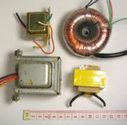
Toroidal cores
Various transformers. The top right is toroidal. The bottom right is from a 12 VAC wall wart supply.
Toroidal transformers are built around a ring-shaped core, which is made from a long strip of silicon steel or permalloy wound into a coil, from powdered iron, or ferrite, depending on operating frequency. The strip construction ensures that the grain boundaries are optimally aligned, improving the transformer's efficiency by reducing the core's reluctance. The closed ring shape eliminates air gaps inherent in the construction of an EI core. The cross-section of the ring is usually square or rectangular, but more expensive cores with circular cross-sections are also available. The primary and secondary coils are often wound concentrically to cover the entire surface of the core. This minimises the length of wire needed, and also provides screening to minimize the core's magnetic field from generating electromagnetic interference.
Ferrite cores are used at higher frequencies, typically between a few tens of kilohertz to a megahertz, to reduce losses, physical size, and weight of switch-mode power supplies.
Toroidal transformers are more efficient (around 95%) than the cheaper laminated EI types. Other advantages, compared to EI types, include smaller size (about half), lower weight (about half), less mechanical hum (making them superior in audio amplifiers), lower exterior magnetic field (about one tenth), low off-load losses (making them more efficient in standby circuits), single-bolt mounting, and more choice of shapes. This last point means that, for a given power output, either a wide, flat toroid or a tall, narrow one with the same electrical properties can be chosen, depending on the space available. The main disadvantage is higher cost.
A drawback of toroidal transformer construction is the higher cost of windings. As a consequence, toroidal transformers are uncommon above ratings of a few kVA. Small distribution transformers may achieve some of the benefits of a toroidal core by splitting it and forcing it open, then inserting a bobbin containg primary and secondary windings.
When fitting a toroidal transformer, it is important to avoid making an unintentional short-circuit through the core. This can happen if the steel mounting bolt in the middle of the core is allowed to touch metalwork at both ends, which could result in a dangerously large current flowing in the bolt.
Windings
In most practical transformers, the primary and secondary conductors are multi-turn coils of conducting wire because each turn of the coil contributes to the magnetic field, creating a higher magnetic flux density than would a single turn. The wire of adjacent turns and different windings must be electrically insulated from each other.
The conducting material used for the winding depends upon the application. Small power and signal transformers are wound with solid copper wire, insulated usually with enamel and sometimes additional insulation. Larger power transformers may be wound with wire, copper or aluminum rectangular conductors, or strip conductors for very heavy currents. High frequency transformers operating in the tens to hundreds of kilohertz will have windings made of Litz wire, to minimize the skin effect losses in the conductors. Large power transformers use multiply-stranded conductors as well, since even at low power frequencies non-uniform distribution of current would otherwise exist in high-current windings. Each strand is insulated from the others, and the strands are arranged so that either at certain points in the winding or throughout the winding, each portion occupies different relative positions in the complete conductor. This "transposition" equalises the current flowing in each strand of the conductor, and reduces eddy current losses in the winding itself. The stranded conductor is also more flexible than a solid conductor of similar size. (see reference (1) below)
For signal transformers the windings may be arranged in a way to minimise leakage inductance and stray capacitance, to improve high-frequency response.
|
|
Windings on both primary and secondary of power transformers may have external connections (called taps) to intermediate points on the winding to allow adjustment of the voltage ratio; taps may be connected to automatic on-load tap changer switchgear for voltage regulation of distribution circuits. Audio-frequency transformers used for distribution of audio to public address loudspeakers have taps to allow adjustment of power supplied to each speaker. A center-tapped transformer is often used in the output stage of an audio power amplifier in a push-pull circuit. Tapped transformers are also used as components of amplifiers, oscillators, and for feedback linearization of amplifier circuits.
Insulation
The turns of the windings must be insulated from each other to ensure that the current travels through the entire winding. The potential difference between adjacent turns is usually small, so that enamel insulation is usually sufficient for small power transformers. In larger transformers additional layers of insulation are used.
The transformer may also be immersed in transformer oil that provides further insulation. To ensure that the insulating capability of the transformer oil does not deteriorate, the transformer casing is completely sealed against moisture ingress. The oil serves as both cooling medium to remove heat from the core and coil and as part of the insulation system.
Shielding
The proximity of the primary and secondary windings can create a mutual capacitance between the windings. Where transformers are intended for high electrical isolation between primary and secondary circuits, an electrostatic shield can be placed between windings to minimize this effect.
Transformers may also be enclosed by magnetic shields, electrostatic shields, or both to prevent outside interference from affecting the operation of the transformer, or to prevent the transformer from affecting the operation of other devices (such as CRTs near the transformer).
Coolant
Small signal transformers do not generate significant amounts of heat. Power transformers rated up to a few kilowatts rely on natural convective air cooling. Transformers handling higher power can be fan-cooled.
Specific provision must be made for cooling of high-power transformers. Some dry transformers are enclosed in pressurized tanks and are cooled by nitrogen or sulfur hexafluoride gas.
The windings of high-power or high-voltage transformers are immersed in transformer oil—a highly-refined mineral oil that is stable at high temperatures. Large transformers to be used indoors must use a non-flammable liquid. Formerly, polychlorinated biphenyl (PCB) was used as it was not a fire hazard in indoor power transformers and it is highly stable. Due to the stability of PCB and its environmental accumulation, it is no longer permitted in new equipment. Today, nontoxic, stable silicone-based oils or fluorinated hydrocarbons may be used, where the expense of a fire-resistant liquid offsets additional building cost for a transformer vault. Other less-flammable fluids such as canola oil may be used but all fire resistant fluids have some drawbacks in performance, cost, or toxicity compared with mineral oil.
The oil cools the transformer, and provides part of the electrical insulation between internal live parts. It has to be stable at high temperatures so that a small short or arc will not cause a breakdown or fire. The oil-filled tank may have radiators through which the oil circulates by natural convection. Very large or high-power transformers (with capacities of millions of watts) may have cooling fans, oil pumps and even oil to water heat exchangers. Oil-filled transformers undergo prolonged drying processes, using vapor-phase heat transfer, electrical self-heating, the application of a vacuum, or combinations of these, to ensure that the transformer is completely free of water vapor before the cooling oil is introduced. This helps prevent electrical breakdown under load.
Oil-filled power transformers may be equipped with Buchholz relays - safety devices sensing gas build-up inside the transformer (a side effect of an electric arc inside the windings) and switching off the transformer.
Experimental power transformers in the 2 MVA range have been built with superconducting windings which eliminates the copper losses, but not the core steel loss. These are cooled by liquid nitrogen or helium.
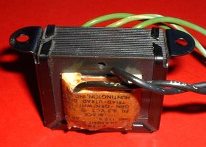
Terminals
Very small transformers will have wire leads connected directly to the ends of the coils, and brought out to the base of the unit for circuit connections. Larger transformers may have heavy bolted terminals, bus bars or high-voltage insulated bushings made of polymers or porcelain. A large bushing can be a complex structure since it must provide electrical insulation without letting the transformer oil leak.
Enclosure
Small transformers often have no enclosure. Transformers may have a shield enclosure, as described above. Larger units may be enclosed to prevent contact with live parts, and to contain the cooling medium (oil or pressurized gas).
Transformer designs
Autotransformers
An autotransformer has only a single winding, which is tapped at some point along the winding. AC or pulsed voltage is applied across a portion of the winding, and a higher (or lower) voltage is produced across another portion of the same winding. While theoretically separate parts of the winding can be used for input and output, in practice the higher voltage will be connected to the ends of the winding, and the lower voltage from one end to a tap. For example, a transformer with a tap at the center of the winding can be used with 230 volts across the entire winding, and 115 volts between one end and the tap. It can be connected to a 230 volt supply to drive 115 volt equipment, or reversed to drive 230 volt equipment from 115 volts. As the same winding is used for input and output, the flux in the core is partially cancelled, and a smaller core can be used. For voltage ratios not exceeding about 3:1, an autotransformer is cheaper, lighter, smaller and more efficient than a true (two-winding) transformer of the same rating.
In practice, transformer losses mean that autotransformers are not perfectly reversible; one designed for stepping down a voltage will deliver slightly less voltage than required if used to step up. The difference is usually slight enough to allow reversal where the actual voltage level is not critical.
By exposing part of the winding coils and making the secondary connection through a sliding brush, an autotransformer with a near-continuously variable turns ratio can be obtained, allowing for very small increments of voltage.
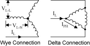
The Y-Δ transform is a mathematical technique to simplify analysis of an electrical network.
Polyphase transformers
For three-phase power, three separate single-phase transformers can be used, or all three phases can be connected to a single polyphase transformer. The three primary windings are connected together and the three secondary windings are connected together. The most common connections are Y-Δ, Δ-Y, Δ-Δ and Y-Y. A vector group indicates the configuration of the windings and the phase angle difference between them. If a winding is connected to earth (grounded), the earth connection point is usually the center point of a Y winding. There are many possible configurations that may involve more or fewer than six windings and various tap connections.
Resonant transformers
A resonant transformer is one that operates at the resonant frequency of one or more of its coils and, usually, an external capacitor. The resonant coil, usually the secondary, acts as an inductor, and is connected in series with a capacitor. If the primary coil is driven by a periodic source of alternating current, such as a square or sawtooth wave, each pulse of current helps to build up an oscillation in the secondary coil. Due to resonance, a very high voltage can develop across the secondary, until it is limited by some process such as electrical breakdown. These devices are therefore used to generate high alternating voltages. The current available from this type of coil can be much larger than that from electrostatic machines such as the Van de Graaff generator and Wimshurst machine. They also run at a higher operating temperature than standard units.
Examples:
- Tesla coil
- Oudin coil (or Oudin resonator; named after its inventor Paul Oudin)
- D'Arsonval apparatus
- Ignition coil or induction coil used in the ignition system of a petrol engine
- Flyback transformer of a CRT television set or video monitor.
- Electrical breakdown and insulation testing of high voltage equipment and cables
Other applications of resonant transformers are as coupling between stages of a superheterodyne receiver, where the selectivity of the receiver is provided by the tuned transformers of the intermediate-frequency amplifiers.
A voltage regulating transformer uses a resonant winding and allows part of the core to go into saturation on each cycle of the alternating current. This effect stabilizes the output of the regulating transformer, which can be used for equipment that is sensitive to variations of the supply voltage. Saturating transformers provide a simple rugged method to stabilize an ac power supply. However, due to the hysteresis losses accompanying this type of operation, efficiency is low.
Instrument transformers
Current transformers
A current transformer is a type of "instrument transformer" that is designed to provide a current in its secondary which is accurately proportional to the current flowing in its primary.
Current transformers are commonly used in electricity meters to facilitate the measurement of large currents which would be difficult to measure more directly.
Current transformers are often constructed by passing a single primary turn (either an insulated cable or a copper busbar) through a well-insulated toroidal core wrapped with many turns of wire. Current transformers are used extensively in the electrical power industry for monitoring of the power grid. The "CT" is described by its current ratio from primary to secondary. Common secondaries are 1 or 5 amperes. The winding often has several taps so that sensitivity to the load may be altered in the future. Often multiple CT's will be installed as a "stack" for various uses (for example, protection devices and revenue metering may use separate CTs). Specially constructed "wideband current transformers" are also used (usually with an oscilloscope) to measure waveforms of high frequency or pulsed currents. One type of specially constructed wideband transformer provides a voltage output that is proportional to the measured current. Another type (called a Rogowski coil) requires an external integrator in order to provide a voltage output that is proportional to the measured current.
Care must be taken that the secondary of a current transformer is not disconnected from its load while current is flowing in the primary as in this circumstance a dangerously high voltage can be produced across the open secondary.
Voltage transformers
Voltage transformers (also called potential transformers) are another type of "instrument transformer". They are used by the electricity supply industry to accurately measure high voltages for metering purposes. They are designed to have a precise turns ratio to accurately step down dangerously high voltages so that metering equipment can be operated at a lower (and safer) potential, typically 100-120 volts. They are designed to present negligible load to the voltage being measured. There are two types of these devices: single pole insulated, which are connected between phase and ground, and two poles insulated, which are connected between two phases.
Pulse transformers
A pulse transformer is a transformer that is optimised for transmitting rectangular electrical pulses (that is, pulses with fast rise and fall times and a constant amplitude). Small versions called signal types are used in digital logic and telecommunications circuits, often for matching logic drivers to transmission lines. Medium-sized power versions are used in power-control circuits such as camera flash controllers. Larger power versions are used in the electrical power distribution industry to interface low-voltage control circuitry to the high-voltage gates of power semiconductors such as TRIACs, IGBTs, thyristors and MOSFETs. Special high voltage pulse transformers are also used to generate high power pulses for radar, particle accelerators, or other pulsed power applications.
To minimise distortion of the pulse shape, a pulse transformer needs to have low values of leakage inductance and distributed capacitance, and a high open-circuit inductance. In power-type pulse transformers, a low coupling capacitance (between the primary and secondary) is important to protect the circuitry on the primary side from high-powered transients created by the load. For the same reason, high insulation resistance and high breakdown voltage are required. A good transient response is necessary to maintain the rectangular pulse shape at the secondary, because a pulse with slow edges would create switching losses in the power semiconductors.
The product of the peak pulse voltage and the duration of the pulse (or more accurately, the voltage-time integral) is often used to characterise pulse transformers. Generally speaking, the larger this product, the larger and more expensive the transformer.
RF transformers (transmission line transformers)
Coils with tickler.
For radio frequency use, transformers are sometimes made from configurations of transmission line, sometimes bifilar or coaxial cable, wound around ferrite or other types of core. This style of transformer gives an extremely wide bandwidth but only a limited number of ratios (such as 1:9, 1:4 or 1:2) can be achieved with this technique.
The core material increases the inductance dramatically, thereby raising its Q factor. The cores of such transformers help improve performance at the lower frequency end of the band. Older style RF transformers sometimes used a third coil (called a tickler winding) to inject feedback into an earlier (detector) stage in antique regenerative radio receivers.
Baluns
Baluns are transformers designed specifially to connect between balanced and unbalanced circuits. These are sometimes made from configurations of transmission line and sometimes bifilar or coaxial cable and are similar to transmission line transformers in constructuion and operation. This style of transformer is frequently used as an impedance matching balun to convert from 300 ohm balanced to 75 ohm unbalanced in FM receivers.
Audio transformers
Transformers are used in audio to match impedances. This is more necessary with valves/vacuum tubes than with solid-state circuitry, as solid-state components are normally used in low output impedance configurations which eliminate the need for matching.
Audio transformers are usually the factor which limit sound quality; electronic circuits with wide frequency response and low distortion are relatively simple to design.
Transformers are also used in DI boxes to match impedance from high impedance instruments (for example, bass guitars) to be able to connect them to a microphone input on the mixing console.
Output transformers
A particularly critical component is the output transformer of an audio power amplifier. Valve circuits for quality reproduction have long been produced with no other (inter-stage) audio transformers, but an output transformer is needed to couple the relatively high impedance (up to a few hundred ohms depending upon configutation) of the output valve(s) to the low impedance of a loudspeaker. (The valves can deliver a low current at a high voltage; the speakers require high current at low voltage.)
For good low-frequency response a relatively large iron core is required; high power handling increases the required core size. Low distortion requires iron of adequate properties; special cores with oriented magnetic domains are used for best results. Good high-frequency response requires carefully designed and implemented windings without excessive leakage inductance or stray capacitance. All this makes for an expensive component.
Output transformerless audio power valve amplifiers are possible (e.g., a design by Julius Futterman), but were rarely used due to other disadvantages.
Early transistor audio power amplifiers often had output transformers, but they were eliminated as designers discovered how to design amplifiers without them.
Speaker transformers
In the same way that transformers are used to create high voltage power transmission circuits that minimize transmission losses, speaker transformers allow many individual loudspeakers to be powered from a single audio circuit operated at higher-than normal speaker voltages. This application is common in public address (e.g., Tannoy) applications. Such circuits are commonly referred to as constant voltage or 70 volt speaker circuits although the audio waveform obviously is constantly changing voltage.
At the audio amplifier, a large audio transformer may be used to step-up the low impedance, low-voltage output of the amplifier to the designed line voltage of the speaker circuit. (For high-powered amps, the amplifier transformer may not be needed.) Then, a smaller transformer at each speaker returns the voltage and impedance to ordinary speaker levels. The speaker transformers commonly have multiple primary taps, allowing the volume at each speaker to be adjusted in a number of discrete steps.
Use of a constant voltage speaker circuit means that there is no need to worry about the impedance presented to the amplifier output (which would clearly be too low if all of the speakers were arranged in parallel and would be a too-complex design problem if the speakers were aranged in series-parallel). The use of higher transmission voltage and impedance means that power lost in the connecting wire is minimized, even with the use of small-gauge conductors (and leads to the term constant voltage as the line voltage doesn't change much as additional speakers are added to the system). Also, the ability to adjust, locally, the volume of each speaker (without the complexity and power loss of an L pad) is a useful feature.
Uses of transformers
- Adaptation of electrical equipment to supply voltages for which it was not made. For example, to use U.S. equipment, designed for 117 V AC, in European countries with 230 V AC. A transformer or autotransformer may be used, or electronic voltage changers which do not use transformers.
- Use inside solid-state equipment which requires low voltages to reduce the main electricity voltage to the required value.
- Use as an external adapter to power low-voltage solid-state equipment from higher-voltage main electricity.